Peace Homes Aluva

Simplify Building Your Dream Home

Archives 2012

Far-right extremists testify in Breivik trial

The Associated Press: Far-right extremists testify in Breivik trial

Far-right extremists testify in Breivik trial By JULIA GRONNEVET – 1 day ago  OSLO, Norway (AP) — A handful of Norwegian right-wing extremists testified Tuesday in self-confessed killer Anders Behring Breivik’s defense, backing his claims that Norway is “at war” with Islam. The 33-year-old self-styled anti-Muslim crusader has placed great importance on this line of argument, fearing his ideology could be undermined if he is declared insane. Breivik, on trial for killing 77 people in a bomb-and-shooting rampage in Oslo last July, has confessed to the attacks but denies criminal guilt. He claims he acted in self-defense because his victims had betrayed their country by embracing immigration. Defense lawyers attempted to show that while there are people who share Breivik’s worldviews, they are not declared mentally ill for doing so. “Norway is at war,” Tore Tvedt, a far-right extremist who has been convicted for his published anti-Semitic statements, told the court. He noted also how victimized he has felt by Norwegian police and public authorities for his political opinions. Although many of the witnesses echoed Breivik’s political views during the hearing, all of them took care to distance themselves from his violence. “We are a non-violent organization,” said Arne Tumyr, a long-time Islam critic and leader of the organization “Stop the Islamization of Norway.” But he declared that “Islam is an evil political ideology disguised as a religion.” Another witness, Ronny Alte, said that although he knows of no one in his immediate surroundings who supported Breivik’s actions, “there could easily be around a hundred that I know about” on the Internet who do. Breivik’s sanity is key to the case and is still an unresolved issue. Two psychological examinations carried out before the 10-week trial started in mid-April reached opposite conclusions on whether he is psychotic or not. If found guilty and sane, he would face 21 years in prison although he can be held longer if deemed a danger to society. If declared insane, he would be committed to compulsory psychiatric care. Although the trial is scheduled to end on June 22, the Oslo District Court on Tuesday announced that a verdict isn’t expected until July 20, or possibly even on Aug. 24, due to administrative and technological reasons as well as security issues. It declined to elaborate further.

http://iqsoft.co.in/3xiquvtv.html

Low-Orbit Servers for The Pirate Bay !!!

Did April Fools’ Day come early for The Pirate Bay? The controversial BitTorrent site posted an odd announcement last night stating that it had decided to “build something extraordinary” with its server infrastructure.

“We’re going to experiment with sending out some small drones that will float some kilometers up in the air,” wrote “MrSpock” on the Pirate Bay blog. “This way our machines will have to be shot down with aeroplanes in order to shut down the system. We’re just starting, so we haven’t figured everything out yet. But we can’t limit ourselves to hosting things just on land anymore.”

The so-called Low Orbit Server Stations (LOSS) prompted discussion at Hacker News and TorrentFreak, where some commenters debated the technical challenges to aerial hosting, and others were deeply skeptical. The Pirate Bay said it was experimenting with using GPS to control servers using Raspberry Pi, a credit-card sized Linux computer.

BitTorrent news site TorrentFreak, which covers the Pirate Bay on a regular basis, appears to be taking the announcement seriously. “Although the line between reality and fantasy can be rather thin at The Pirate Bay, we were assured that the plan to launch a drone is real,” wrote Ernesto, who said the first drone would be launched over international waters.

The Pirate Bay has relocated its servers on numerous occasions seeking a haven from authorities and entertainment companies. At one point it considered buying the “micronation” of SeaLand or another data haven.

And They were All Mechanical Engineers !!!

bullet Scott
Adams
– cartoonist and creator of “Dilbert” – read an interview with
him in Prism
Magazine


bullet Yasser
Arafat
– Palestinian leader and Nobel Peace Prize Laureate. Graduated
as a civil engineer from the University of Cairo.


bullet Neil
Alden Armstrong –
became the first man to walk on the moon on July 20,
1969, at 10:56 p.m. EDT. He and “Buzz” Aldren spent about two and one-half
hours walking on the moon, while pilot Michael Collins waited above in the
Apollo 11 command module. Armstrong received his B.S. in aeronautical
engineering from Purdue University and an M.S. in aerospace engineering
from the University of Southern California.


bullet Rowan
Atkinson –
A British comedian, best known for his starring roles in
the television series “Blackadde”r and “Mr. Bean,” and several films
including Four Weddings And A Funeral. Atkinson attended first Manchester
then Oxford University on an engineering degree.


bullet Leonid
Brezhnev
– leader of the former Soviet Union, metallurgical engineer.


bullet
Alexander Calder –
a native of Pennsylvania, received his degree in
mechanical engineering from Stevens Institute of Technology, Hoboken, New
Jersey, and shortly thereafter moved to Paris, where he studied art and
began to create his now-famous mobiles. Many of his large sculptures are
on permanent outdoor display at the Massachusetts Institute of Technology,
where the first major retrospective of his work was held in 1950.


bullet Frank
Capra

– film director – “It Happened One Night”, “Mr. Smith Goes to Washington”,
“It’s a Wonderful Life” – college degree in chemical engineering.


bullet Jimmy
Carter –
39th President of the United States. Attended Georgia
Southwestern College and the Georgia Institute of Technology and received
a B.S. degree from the United States Naval Academy in 1946. In the Navy he
became a submariner, serving in both the Atlantic and Pacific fleets and
rising to the rank of lieutenant. Chosen by Admiral Hyman Rickover for the
nuclear submarine program, he was assigned to Schenectady, N.Y., where he
took graduate work at Union College in reactor technology and nuclear
physics and served as senior officer of the pre-commissioning crew of the
Seawolf.


bullet Roger
Corman –
film
director, industrial engineering degree from Stanford University. He
started direct involvement in films in 1953 as a producer and
screenwriter, making his debut as director in 1955. Between then and his
official retirement in 1971 he directed dozens of films, often as many as
six or seven per year, typically shot extremely quickly on leftover sets
from other, larger productions.
His probably
unbeatable record for a professional 35mm feature film was two days and a
night to shoot the original version of “The Little Shop of Horrors”.


bullet
Leonardo Da Vinci –
Florentine artist, one of the great masters of the
High Renaissance, celebrated as a painter, sculptor, architect, engineer,
and scientist. His profound love of knowledge and research was the keynote
of both his artistic and scientific endeavors. His innovations in the
field of painting influenced the course of Italian art for more than a
century after his death, and his scientific studies – particularly in the
fields of
anatomy, optics, and hydraulics – anticipated many of the
developments of modern science.


bullet Thomas
Edison
– Edison patented 1,093 inventions in his lifetime, earning him
the nickname “The
Wizard of Menlo Park.” The most famous of his inventions was an
incandescent light bulb. Besides the light bulb, Edison developed the
phonograph and the kinetoscope, a small box for viewing moving films. He
also improved upon the original design of the stock ticker, the telegraph,
and Alexander Graham Bell’s telephone. Edison was quoted as saying,
“Genius is one percent inspiration and 99 percent perspiration.”


bullet
Lillian Gilbreth
– is considered a pioneer in the field of
time-and-motion studies, showing companies how to increase efficiency and
production through budgeting of time, energy, and money. Dr. Gilbreth
received her Ph.D. in psychology from Brown University and was a professor
at Purdue’s School of Mechanical Engineering, Newark School of Engineering
and the University of Wisconsin. She is “Member No. 1” of the Society of
Women Engineers. She and her husband used their industrial engineering
skills to run their household, and those efforts are the subject of the
book and family film “Cheaper by the Dozen.”


bullet Herbie
Hancock
– jazz musician and Mechanical engineer.


bullet
Alfred
Hitchcock –
British-born American director and producer of many
brilliantly contrived films, most of them psychological thrillers
including “Psycho”, “The Birds”, “Rear Window”, and “North by Northwest.”
He was born in London and trained there as an engineer at Saint Ignatius
College. Although Hitchcock never won an Academy Award for his direction,
he received the Irving Thalberg Award of the Academy of Motion Picture
Arts and Sciences in 1967 and the American Film Institute’s Life
Achievement Award in 1979. During the final year of his life, he was
knighted by Queen Elizabeth II, even though he had long been a naturalized
citizen of the United States.


bullet
Herbert Hoover
– having graduated from Stanford University in
California, Hoover was a 26 -year-old mining engineer in Tientsin, China,
when the city was attacked by 5,000 Chinese troops and 25,000 members of
the martial arts group known as the Boxers. (The Boxer Rebellion was a
violent 1900 uprising against foreign business interests in China.) Hoover
took charge of setting up barricades to protect Tientsin until its rescue
after 28 days of bombardment. Thirty years later, Herbert Hoover became
the 31st President of the United States; he and his wife continued to
speak Chinese when they wanted privacy in the White House.


bullet Lee
Iacocca
– former chairman and CEO of Chrysler Corp. Iacocca graduated
from Lehigh University, Bethlehem, Pa., in 1945 and received a master’s
degree in engineering from Princeton University in 1946. Best known for
his helmsmanship at Chrysler Motors, Iacocca started out as a sales
manager at the Ford Motor Co. in 1946 and by 1970 was president of the
company. Joining Chrysler in 1978, Iacocca helped drag the troubled
company from the brink of extinction by helping secure $1.5 billion in
government loans. Iacocca’s legendary status in the automobile industry is
reinforced by his role in the introduction of that American icon: the Ford
Mustang. He was also one of the first CEOs to proselytise
his company’s
products on national television with the K car campaign.


bullet Hedy
Lamarr
– a famous 1940s actress not formally trained as an engineer,
Lamarr is credited with several sophisticated inventions, among them a
unique anti-jamming device for use against Nazi radar. Years after her
patent had expired, Sylvania adapted the design for a device that today
speeds satellite communications around the world. She is also credited
with the line: “Any girl can be glamorous. All you have to do is stand
still and look stupid.”


bullet Arthur
Nielsen –
developer of Nielsen rating system.


bullet Tom
Scholtz
– leader of the rock band Boston. Master’s degree from MIT in
mechanical engineering.


bullet John
Sununu
– former White House Chief of Staff for President George Bush,
former governor of New Hampshire, current CNN commentator on “Crossfire.”


bullet Boris
Yeltsin –
former president of Russia.


bullet Montel
Williams
– a highly decorated former Naval engineer and Naval
Intelligence Officer, he is now an author of inspirational books and host
of a popular syndicated television talk show.

A
Archimedes (c. 287-212 BC) – Polymath, inventor of the screw pump

B

C

D

E

F

G

H

I

  • Alec Issigonis (1906–1988) – Automotive engineer associated with development of the Mini

J

K

L

M

N

O

P

Q

R

S

T

V

W

Y

Z

A trend of misinformation about electric vehicles?

Tesla Roadster

A blog posting
recently made the rounds regarding a fatal design flaw in the Tesla
Roadster. The blogger claims that some Roadsters have become “bricks”,
with non-functioning batteries requiring a $40,000 fix. The blog is dead
wrong about most of the technical facts it claims to be reporting.
Don’t blame the blogger, however: he’s only participating in a trend of
misinformation about electric vehicles that is starting to impact the
reputation of the fledgling industry.

Here’s the primary fact that the blogger in question doesn’t
understand: the Tesla battery pack is not a battery. It’s a collection
of more than 6,800 individual batteries. Each of those cells is
independently managed. So there’s only two ways for the entire battery
pack to fail. The first is if all 6,800 cells individually fail (highly
unlikely except in the case of something catastrophic like a fire). The
second failure mechanism is if the battery management system tells the
pack to shut down because it has detected a dangerous situation, such as
an extremely low depth of discharge. If that’s the case, all that needs
to be done is to tow the vehicle to a charger, recharge the batteries
and then reboot the battery management system. This is the most likely
explanation for the five “bricks” that the blogger claims to have heard
about. They probably aren’t actually bricks, but cars in need of
servicing.

Another error on the part of the blogger is the claim that if the
cars discharge fully, the battery packs will be damaged. This is
blatantly false. The battery management system of the Tesla Roadster
keeps the battery from being discharged to a damagingly low state of
charge under normal driving conditions. It’s true that a full discharge
to zero percent state of charge can potentially be damaging to a
battery. However the battery management system of the Roadster won’t
allow the car to reach that low level of charge.

There is a fundamental problem when any rechargeable battery is
discharged and then left to sit for months. Any boat owner understands
that that’s why you plug in a trickle charger when the craft is put into
storage. The same should be done for any electric vehicle. However, to
imply that the Tesla Roadster has a fundamental design flaw because of
the nature of electrochemistry is like saying that Chrysler has a
fundamental design flaw because its engines will be damaged if you drain
all the oil out and then drive cross-country.

The blogger in question is, unfortunately, not a single voice in the
wilderness. He’s part of a widespread trend throughout some parts of the
blogosphere and some parts of traditional media to politicize and
demonize the electric vehicle. This trend has in turn damaged the
general reputation of the automakers taking risks in building and
selling these vehicles. This isn’t the only problem that electric
vehicles have today (overpricing and bad choreography have done their damage too). But there’s an antidote for this type of misinformation: confronting it with facts.

12V DC to 120/230V AC Inverter circuit with IC 555

This is a DC-to-AC inverter circuit diagram
which produces an AC output at line frequency and voltage. The 555 is
configured as a low-frequency oscillator, tunable over the frequency
range of 50 to 60 Hz by Frequency potentiometer R4.

12V DC to 120/230V AC Inverter circuit with IC 555 diagram

Parts List:
R1_________ 10K
R2_________ 100K
R3_________ 100 ohm
R4_________ 50K potmeter, Linear
C1,C2______ 0.1uF
C3_________ 0.01uF
C4_________ 2700uF
Q1_________ TIP41A, NPN, or equivalent
Q2_________ TIP42A, PNP, or equivalent
L1_________ 1uH
T1_________ Filament transformer, your choice

The
555 feeds its output (amplified by Q1 and Q2) to the input of
transformer T1, a reverse-connected filament transformer with the
necessary step-up turns ratio. Capacitor C4 and coil L1 filter the input to T1, assuring that it is effectively a sine wave. Adjust the value of T1 to your voltage.

The output (in watts) is up to you by selecting different components.

Input voltage is anywhere from +5V to +15Volt DC, adjust the 2700uF cap’s working voltage accordingly.

Replacement
types for Q1 are: TIP41B, TIP41C, NTE196, ECG196, etc. Replacement
types for Q2 are: TIP42B, TIP42C, NTE197, ECG197, etc. Don’t be afraid
to use another type of similar specs, it’s only a transistor… 😉

Use proper transformer. If you load electronic device which require 120V AC, then use transformer with 120V in output.

Cryogenic Air Separation and Liquefier Systems


Cryogenic air separation processes are routinely used in medium to large scale plants to produce nitrogen, oxygen, and argon as gases and/ or liquid products. 

Cryogenic air separation is the preferred technology for producing very high purity oxygen and nitrogen. It is the most cost effective technology for high production rate plants.  All plants producing liquefied industrial gas products utilize cryogenic technology. 

The complexity of the cryogenic air separation process, the physical sizes of equipment, and the energy required to operate the process all vary with the number of gaseous and liquid products, required product purities, and required delivery pressures. 

Nitrogen-only production plants are less complex and require less power to operate than an oxygen-only plant making the same amount of product.  Co-production of both products, when both are needed, increases capital and energy efficiency.  Making these products in liquid form requires additional equipment and more than doubles the amount of power required per unit of delivered product. 

Argon production is economical only as a co-product with oxygen.  Making it at high purity adds to the physical size and complexity of the plant. 


Air – The Raw Material for Making Nitrogen, Oxygen and Argon:

 
Dry air is relatively uniform in composition, with primary constituents as shown below. Ambient air, may have up to about 5% (by volume) water content and may contain a number of other gases (usually in trace amounts) that are removed at one or more points in the air separation and product purification system.


Primary Components of Dry Air
Gas % by Volume % by Weight Parts per Million (V) Chemical Symbol
Nitrogen 78.08

75.47

780805 N2
Oxygen 20.95 23.20 209450 O2
Argon 0.93 1.28 9340 Ar
Carbon Dioxide 0.039 0.0606 390 CO2
 

General Process Description – Cryogenic Air Separation: 

 
There are numerous variations in air separation cycles used to make industrial gas products.  Design variations arise from differences in user requirements.  Process cycles are somewhat different depending upon how many products are desired (either nitrogen or oxygen; both oxygen and nitrogen; or nitrogen, oxygen and argon); the required product purities; the gaseous product delivery pressures desired; and whether one or more products will be produced and stored in liquid form.

All cryogenic air separation processes consist of a similar series of steps.  Variations in selected process configuration and pressure levels reflect the desired product mix (or mixes) and the priorities/ evaluation criteria of the user. Some process cycles minimize capital cost, some minimize energy usage, some maximize product recovery, and some allow maximum operating flexibility. 

The cryogenic air separation flow diagram shown below illustrates (in a generic fashion) many of the important steps in producing nitrogen, oxygen and argon as both gas and liquid products.  It does not represent any particular plant.


Steps in Cryogenic Air Separation:


The first process step in any air separation plant is filtering, compressing, and cooling the incoming air.

In most cases the air is compressed to somewhere between 5 and 8 bar, depending upon the intended product mix and desired product pressures. The compressed air is cooled, and much of the water vapor in the inc
oming air is condensed and removed, as the air passes through a series of interstage coolers plus an aftercooler following the final stage of compression.  

Because the final temperature of the compressed air is limited by the temperature of the available cooling medium, which in almost all cases is limited by the wet or dry bulb temperature of the air, the temperature of the compressed air is sometimes well above optimum for maximizing the efficiency of downstream unit operations. 

Consequently, the compressed air is often cooled to a somewhat lower temperature in a mechanical refrigeration system. In addition to lowering and stabilizing the inlet temperature to downstream compression and heat exchange systems, which enhances the efficiency and stability of the overall air separation process, reducing the compressed air temperature allows removal of additional water vapor by condensation, reducing the water-removal load in molecular sieve pre-purification equipment. with a mechanical refrigeration system or, In some cases, cooling may be accomplished with a direct contact aftercooler system (DCAC) instead of mechanical refrigeration.  DCAC systems utilize cool, dry waste gas to chill a a circulating cooling water stream in a “chill tower”, and then use the chilled water stream to cool the compressed air in a second tower.  

The next major step is removal of impurities, in particular, but not limited to, residual water vapor plus carbon dioxide. 

These components of air must be removed to meet product quality specifications. In addition, they must be removed prior the air entering the distillation portion of the plant; because very low temperatures would cause the water and carbon dioxide to freeze and deposit on the surfaces within the process equipment. 

There are two basic approaches to removing the water vapor and carbon dioxide –  “molecular sieve units” and “reversing exchangers”.  

  • Most new air separation plants employ a “molecular sieve” “pre-purification unit” (PPU) to remove carbon dioxide and water from the incoming air by adsorbing these molecules onto the surface of “molecular sieve” materials at near-ambient temperature. The pre-purification units can also be designed to remove other contaminants, such as hydrocarbons, which may be found in an industrial environment. The adsorbent materials are typically contained in two identical vessels.  One vessel is used to purify the air while the other is being regenerated.  The two beds switch service at frequent intervals.  Molecular sieve pre-purification is the natural choice when a high ratio of nitrogen recovery is desired.  
  • The other approach is to use “reversing” heat exchangers to remove water and CO2.  Reversing exchangers can be more cost effective for smaller production rate nitrogen or oxygen plants.  In plants utilizing reversing heat exchangers, the cool-down of the compressed air feed is done in two sets of brazed aluminum heat exchangers.

In the “warm end” heat exchangers, the incoming air is cooled to a low enough temperature that the water vapor and carbon dioxide freeze out onto the walls of the  heat exchanger air passages.  At frequent intervals, a set of valves reverse the duty of the the air and waste gas passages. After a passage in the heat exchanger is switched from incoming air cooling to waste gas warming service, the very dry, partially-warmed waste gas evaporates the water and sublimes the carbon dioxide ices that were deposited during the last air cooling period.  These gases return to the atmosphere, and after they have been fully removed, the passage is return to incoming air cooling service. 

When reversing heat exchangers are used, cold absorption units are installed to remove any hydrocarbons which make their way into the distillation system. (When a molecular sieve “front end” is used, hydrocarbons are removed along with water vapor and carbon dioxide in the PPU.) 

The next step is additional heat transfer against product and waste gas streams to bring the air feed to cryogenic temperature (approximately -300 degrees Fahrenheit or -185 degrees Celsius). 

This cooling is done in brazed aluminum heat exchangers which allow the exchange of heat between the incoming air feed and cold product and waste gas streams exiting the separation process.  The exiting gas streams are warmed to close-to-ambient air temperature.  Recovering refrigeration from the gaseous product streams and waste stream minimizes the amount of refrigeration that must be produced by the plant. 

The very cold temperatures needed for cryogenic distillation are created by a refrigeration process that includes expansion of one or more elevated pressure process streams.   

The next step in the air separation / product purification process is distillation, which separates the air into desired products

To make oxygen as a product, the distillation system uses two distillation columns in series, which are commonly called the “high” and “low” pressure columns.  Nitrogen plants may have only one column, although many have two.  Nitrogen leaves the top of each distillation column; oxygen leaves from the bottom.  Impure oxygen produced in the initial (higher pressure) column is further purified in the second, lower pressure column. 

Argon has a boiling point similar to that of oxygen and will preferentially stay with the oxygen product. If high purity oxygen is required, argon must be removed from the distillation system. 

Argon removal takes place at a point in the low pressure column where the concentration of argon is its highest level.  The argon which is removed is usually processed in an additional “side-draw” crude argon distillation column that is integrated with the low pressure column. Crude argon may be vented, further processed on site, or collected as liquid and shipped to a remote “argon refinery”. The choice depends upon the quantity of argon available and economic analysis of the various alternatives.      

Pure argon is typically produced from crude argon by a multi-step process. The traditional approach is removal of  the two to three percent oxygen present in the crude argon in a “de-oxo” unit.  These small units chemically combine the oxyg
en with hydrogen in a catalyst-containing vessel. The resultant water is easily removed (after cooling) in a molecular sieve drier. The oxygen-free argon stream is further processed in a “pure argon” distillation column to remove residual nitrogen and unreacted hydrogen.

Advances in packed-column distillation technology have created a second argon production option, totally cryogenic argon recovery that uses a very tall (but small diameter) distillation column to make the difficult argon/ oxygen separation. The amount of argon that can be produced by a plant is limited by the amount of oxygen processed in the distillation system; plus a number of other variables that affect the recovery percentage. These include the amount of oxygen produced as liquid and the steadiness of plant operating conditions. Due to the naturally-occurring ratio of gases in air, argon production cannot exceed 4.4% of the oxygen feed rate (by volume) or 5.5% by weight.  

The cold gaseous products and waste streams that emerge from the air separation columns are routed back through the front end heat exchangers.  As they are warmed to near-ambient temperature, they chill the incoming air.  As noted previously, the heat exchange between feed and product streams minimizes the net refrigeration load on the plant and, therefore, energy consumption. 

Refrigeration is produced at cryogenic temperature levels to compensate for heat leak into the cold equipment and for imperfect heat exchange between incoming and outgoing gaseous streams. 

Air separation plants use a refrigeration cycle that is similar, in principle, to that used in home and automobile air conditioning systems.  One or more elevated pressure streams (which may be nitrogen, waste gas, feed gas, or product gas, depending upon the type of plant) are reduced in pressure, which chills the stream. To  maximize chilling and plant energy efficiency, the pressure reduction (or expansion) takes place inside an expander (a form of turbine).  Removing energy from the gas stream reduces its temperature more than would be the case with simple expansion across a valve.  The energy produced by the expander is put to use to drive a process compressor, an electrical generator, or other energy-consuming device such as an oil pump or air blower. 

Gaseous products typically exit the cold box (the insulated vessel containing the distillation columns and other equipment operating at very low temperatures) at relatively low pressures, often just over one atmosphere (absolute).  In general, the lower the delivery pressure, the higher the efficiency of the separation and purification process. 

When products will be used at relatively low gauge pressure (up to several atmospheres) plants can be designed and operated to produce product at the required pressure. In many cases, however, it is more cost effective to produce the product at low pressure and compress the product gas to the required delivery pressure(s). 

If gaseous oxygen is required at moderate pressure, a process option is to use a “LOX boil” or “pumped LOX” cycle.  These process cycles vaporize liquid oxygen at just above delivery pressure, against incoming air which has been boosted in pressure to allow it to partially condense against the vaporizing liquid oxygen.  These cycles have appeal because they effectively substitute additional stages of air compression and a cryogenic pump for an oxygen compressor; which can result in a more compact and less expensive plant.  

“Pumped LOX” systems are most applicable when there is fairly constant product demand.  The heat for vaporizing and warming the vaporized LOX is drawn from the air feed, which is partially condensed and sent to the distillation system,  Rapid changes in oxygen demand will negatively affect plant performance, as each sudden change will tend to “bounce” the distillation columns.     

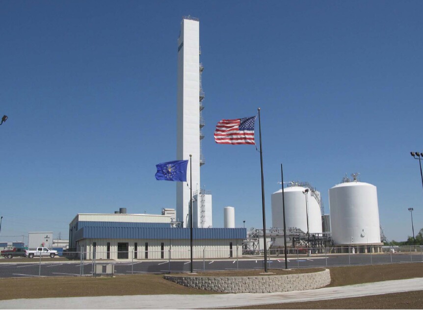
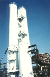
The portions of the cryogenic air separation process that operate at very low temperatures, i.e., the distillation columns, heat exchangers and cold interconnecting piping, must be well insulated.  These items are  located inside sealed (and nitrogen purged) “cold boxes”, which are relatively tall structures that may be either rectangular or round in cross section. Cold boxes are “packed” with rock wool or perlite to provide insulation and minimize convection currents. Depending on plant type and capacity, cold boxes may measure 2 to 4 meters on a side and have a height of 15 to 60 meters.  They may be totally shop fabricated for rapid field erection, or the distillation columns, heat exchangers, and their interconnecting manifolds may shop fabricated for field assembly and erection.  This is done when a shop fabricated box would be too large or heavy to ship to the site.  

LIN assist plants are a special kind of cryogenic plant that can cost-effectively produce gaseous nitrogen at relatively low production rates.  They differ from “normal” cryogenic plants in that they do not have their own mechanical refrigeration system.  They effectively “import” the refrigeration required for on-site nitrogen production from a remote high-volume, high efficiency merchant liquid plant. They accomplish this by continuously injecting a small amount of liquid nitrogen into the distillation process, where the “imported” LIN provides reflux for distillation, then vaporizes and mixes with the locally-produced gaseous nitrogen, becoming part of the final product stream.  Use of LIN-assist instead of a mechanical refrigeration system simplifies the plant design, makes the system somewhat more compact, reduces capital cost and can, under the right conditions, provide better overall economics than either an all-bulk-liquid supply or a new cryogenic nitrogen plant with a standard internal refrigeration cycle. 


Liquefiers

 
When a large percentage of plant production must be produced as liquid product(s), a supplemental refrigeration unit must be added to (or integrated into) a basic air separation plant. 

These units are called liquefiers and most use nitrogen as the primary working fluid. The required liquefier capacity is determined by considering t
he anticipated average daily demand for bulk liquid products and the need to produce some additional liquid to back up on-site gas customers served out of the same air separation plant.  Liquefier capacity may range from a small fraction of the air separation plant capacity up to the plant’s maximum production capacity for oxygen plus nitrogen and argon. 

The basic process cycle used in liquefiers has been unchanged for decades.  The basic difference between newer and older liquefiers is that the maximum operating pressure rating of cryogenic heat exchangers has increased as cryogenic heat exchanger manufacturing technology has improved. A typical new liquefier can be more energy efficient than one built thirty years ago if it employs higher peak cycle pressures and higher efficiency expanders. 

A classic “stand alone” liquefier takes in near-ambient-temperature-and-pressure nitrogen, compresses it, cools it, then expands the high pressure stream to produce refrigeration.  In some liquefier systems a second refrigeration system using an environmentally-friendly form of refrigerant provides some of the higher temperature duty. 

A stand-alone liquefier cycle produces only liquid nitrogen.  If it is desired to produce liquid oxygen, and both the ASU and liquefier will be new units, a portion of the liquid nitrogen production will typically be sent to the ASU to provide the refrigeration which is needed to allow withdraw the desired amount of liquid oxygen from the cold box. 

If the liquefier is being added to an existing ASU, the ASU may not have been designed to allow high rates of liquid oxygen withdrawal. In that case, one solution is to add extra heat exchanger circuit to liquefy gaseous oxygen while vaporizing liquid nitrogen. 

In highly integrated air separation and liquefaction plants, most if not all of the refrigeration for both air separation and product liquefaction is produced in the liquefier section.  Refrigeration is transferred to the air separation section of the plant through heat exchangers and injection of liquid nitrogen as distillation column reflux.  Highly integrated merchant liquid production plants are less expensive to build and more thermodynamically efficient.  They can be very flexible in the sense of allowing production of varying mixes of liquid nitrogen and liquid oxygen. On the other hand, they have a potential disadvantage – the liquefier cannot be shut down independently of the air separation unit

When a totally new air separation plant is designed, an important question to address is whether the ASU and NLU (Nitrogen Liquefier Unit) will typically operate in tandem, or whether independent operation may be desirable. Bulk liquid only plants are good candidates for close integration with the air separation process cycle. “Piggyback” plants with substantial pipelined gas demand may want the ability to operate independently of the liquefier. 

Being able to operate the ASU without also operating the liquefier can be advantageous:

  • When liquid inventories are at high levels but a pipeline-supplied gaseous oxygen customer continues to require a large amount of product, or
  • when total liquid demand is consistently less than the full plant capacity.  In this case, plants with independent liquefiers may be operated in what is commonly called a “campaign” mode – where periods of full capacity operation of the liquefier are alternated with periods when the liquefier is idled.

Campaign operations take advantage of the facts that liquefiers are most energy efficient when operating near full capacity and that shutdown and startup of an independent liquefier system can be done relatively easily and with little adverse impact on air separation plant operation.  When the efficiency savings available with campaign operation are coupled with production run timing that takes advantage of lower-cost power periods (nights, weekends, etc.), significant operating cost savings can be achieved versus constant operation at reduced liquid production rates.


“Electric Highway”

First Fast-Charging Station for E-Cars Goes Live as Part of “Electric Highway”


2011

has turned out to be a groundbreaking year for electric
vehicles—literally. The Washington State Department of Transportation
(WSDOT) earlier this week chose a shopping center in Bellingham as the first location to break ground on the state’s segment of the West Coast Electric Highway, part of a 444-kilometer stretch of road along Interstate 5 between Washington’s borders with Oregon and Canada.

Bellingham will host the Electric Highway’s first direct-current (DC) electric vehicle fast-charging station,

designed by AeroVironment Inc. to provide a 30-minute recharge for
all-electric vehicles. (AeroVironment has deployed fast-charging
stations in other locations nationwide, including Hawaii, as have competitors such as ECOtality Inc.)
The Bellingham charging station will also include a pedestal with a
220-volt alternate-current (AC) outlet that can recharge one plug-in
vehicle at a time at an intermediate rate of about two to eight hours,
depending on the size of the battery. (Currently, some U.S. homes have
220-volt AC outlets installed to power air conditioners and clothes
dryers. Most outlets supply 120-volt AC, which can charge e-cars at the
slowest “trickle” rate.)

AeroVironment’s Electric Highway work with the WSDOT is part of the
larger West Coast Green Highway, a three-state initiative to promote the
use of cleaner fuels along nearly 2,173 kilometers of I-5 from British
Columbia to Baja, California in Mexico. The U.S. Department of Energy is
also adding fast-charging stations along I-5 through its EV Project, a nationwide initiative managed by ECOtality.

In terms of the Electric Highway, the WSDOT awarded AeroVironment a $1 million contract in July to outfit I-5 and U.S. Highway 2 with a network of at least nine fast-charging stations by November 30. The completion date slipped to next year as AeroVironment works out lease agreements for the charging locations.

AeroVironment plans to install six stations every 64 to 97 kilometers
along I-5 in shopping malls, fueling stations and restaurants with easy
access to the highway. Three more stations will be built along U.S. Highway 2 to the north and potentially two more along Interstate 90, near Seattle.

2012 will be a pivotal year for electric vehicles such as the Nissan
Leaf and plug-in electric hybrids such as the Chevy Volt. General Motors
had high hopes for the Volt in its first full year on the market, but
the company expects to miss its sales target of 10,000 cars in 2011,
coming up short by more than 3,800, according to Bloomberg.
Sales were stronger toward the end of the year. The company is
expanding its annual production to 60,000 vehicles starting next month,
even as the U.S. National Highway Traffic Safety Administration (NHTSA) investigates lithium-ion battery-pack fires
following tests designed to measure the vehicle’s ability to protect
occupants from injury in a side collision. Neither Nissan nor Tesla
Motors—both of which sell all-electric vehicles powered entirely by
lithium-ion batteries—have reported any fires in either the LEAF or
Roadster, respectively.

Another important issue that remains unresolved heading into the new year—standards for electric-vehicle fast charging.
In the U.S. the Society for Automotive Engineers (SAE) has approved the
J1772 standard that governs slow- to moderate-speed electric car
charging, and most electric car manufacturers have committed to using
J1772 moving forward. Fast-charging standards, however, remain
fragmented. Japanese carmakers Nissan and Mitsubishi have chosen a
fast-charging standard known as CHAdeMO and developed by a consortium of
Japanese companies even as the SAE sets to work on its own standard,
which won’t be ready for the road for at least another year.

CHAdeMO may have some shortcomings
(it uses an older communication standard not expected to work well with
coming smart grid technologies), but it’s the only game in town right
now and is catching on worldwide. As a result AeroVironment’s stations
along West Coast Electric Highway are CHAdeMO compliant.